To check the error of you soundcard, use analysis software that is able to calculate the deviation of the sample rate in ppm. Try to avoid sound cards that are completely out of tolerance.
When W-CODE uses low-cost sound cards as a signal source, sampling frequency errors will most likely occur. For commonly available sound cards, the sampling frequency may vary up to one percent of the nominal value. This behavior prevents decoding or introduces additional errors. Complex signals like the MIL-Standard and STANAG waveforms are heavily affected.
In previous versions of W-CODE the “SR Fine Tuning” feature was used to correct the sampling rate, but adjusting the rate was very difficult due to a substantial time lag between the adjustment taking place and the display being updated. To remedy this problem, a new feature has been introduced under “Configuration | SR Calibration”. The new feature utilizes an AM demodulator, which demodulates the pulses of a reference signal - the output, which resembles a fax image, is displayed in a calibration window. The degree and the direction of slanting of vertical lines are a measure of the amount and the sign of the deviation between the sound card sampling frequency and the reference signal. The values are stored and used for all future decoding.
Signal thresholds can be set with a tunable band pass filter, which may be placed anywhere in the spectrum with the desired bandwidth. The settings affect the blurring of pulse edges.
Reference signals which may be used include weather fax transmissions and time signals, e.g., CHU, DCF77, MSF, HBG etc. For instance, CHU transmits a short tone pulse every second. If the band pass filter is tuned to the frequency of this tone, a straight, vertical line will be visible if the sampling rate of the sound card is correct. If the line is slanted to either side the sampling rate is offset. To adjust the sampling rate, use “Options | Fine Tune” until the vertical line representing the reference signal is straight.
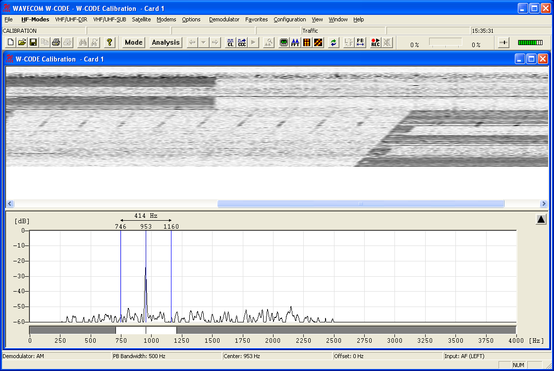
Example: CHU signal
First adjust the center frequency and the bandpass filter settings. You will notice that the vertical lines are skewed.
Press “Options | Fine Tune…” and use the slider to adjust the vertical lines so they become perpendicular to the time axis of the calibration window.
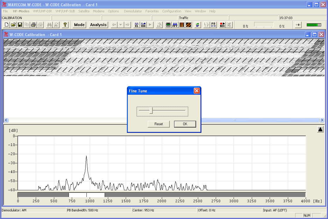
Note: The full range of the “Fine Tune” process is 0.1% deviation. For deviations larger than this use “Fine Tune” repeatedly until the desired effect has been achieved.
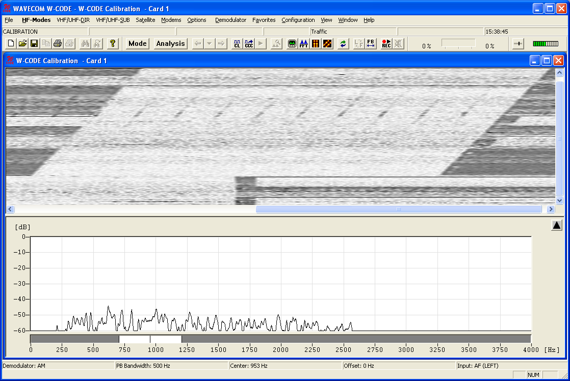
If you succeeded in correcting the sampling rate, i.e., the vertical lines have been straightened and are perpendicular to the time axis, press “OK” to save the measured value.
As the sampling rate calibration feature utilizes an AM demodulator, input level should be as high as possible, resulting in a high level of contrast which facilitates the adjustments. If necessary use the “Demodulator” menu to adjust the AM gain and offset.
These two functionalities (SR Fine Tuning and SR Calibration) are not available when W-PCI or W-PCIe is used.