STANAG-4285 is specified by the NATO (North Atlantic Treaty Organization) Military Agency for Standardization in "Characteristics of 1200 / 2400 / 3600 Bits per Second Single Tone Modulators / Demodulators for HF Radio Links" (16. February 1989).
|
Parameter |
Value |
|
Frequency range |
HF |
|
Operation modes |
Broadcast/Simplex FEC |
|
Modulation |
8-PSK |
|
Center frequency |
1800 Hz |
|
Symbol rate |
2400 Bd |
|
Receiver settings |
DATA, CW, LSB or USB |
|
Input format(s) |
AF, IF |
The modulation technique used in this mode consists of phase shift keying (8-PSK) of a single tone sub-carrier of 1800 Hz. The modulation speed (symbol rate) is always 2400 Bd.
Using different M-PSK modulations and FEC (Forward Error Correction) coding rates, serial binary user information (raw data) accepted at the line side input can be transmitted at different user data rates.
STANAG 4285 single tone waveform has the following characteristics which may be selected from Options |Frame Format...:
|
Baud Rate |
User data rate (bps) |
User data rate (bps) |
FEC coding rate |
Interleaver |
No. of unknown 8-phase symbols (User Data) |
No. of known 8-phase symbols (Channel Probe) |
|
2400 |
2400 |
3 (8-PSK) |
2 / 3 |
SHORT or LONG |
32 |
16 |
|
2400 |
1200 |
2 (QPSK) |
1 / 2 |
SHORT or LONG |
32 |
16 |
|
2400 |
600 |
1 (BPSK) |
1 / 2 |
SHORT or LONG |
32 |
16 |
|
2400 |
300 |
1 (BPSK) |
1 / 4 |
SHORT or LONG |
32 |
16 |
|
2400 |
150 |
1 (BPSK) |
1 / 8 |
SHORT or LONG |
32 |
16 |
|
2400 |
75 |
1 (BPSK) |
1 / 16 |
SHORT or LONG |
32 |
16 |
|
2400 |
3600 |
3 (8-PSK) |
No coding |
ZERO |
32 |
16 |
|
2400 |
2400 |
2 (QPSK) |
No coding |
ZERO |
32 |
16 |
|
2400 |
1200 |
1 (BPSK) |
No coding |
ZERO |
32 |
16 |
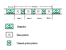
The user data is transmitted using a continuous frame structure. Each frame begins with a 33.33 ms preamble containing 80 symbols, the next 176 symbols are divided into four 32-symbol data segments and three 16-symbol channel probe segments.
At the end of transmission, a certain bit-pattern (in hexadecimal notation, 4B65A5B2, MSB first) is sent to mark the end of message (EOM). The EOM sequence is followed by flush bits, which are for FEC coder flushing and for the complete transmission of the remainder of the interleaver data block.
In most cases FEC and interleaver are used to combat the effects of fading, frequency shift, multipath effects and burst noise. User data is in this case first FEC encoded, interleaved, then mapped into PSK symbol and transmitted in 32 symbol data segment. The 16 symbol channel segment transmitted between every data segment has a known PSK pattern. Its purpose is to keep the demodulator, mainly the equalizer, on track in spite of adverse propagation conditions during the HF transmission.
After the 176 symbol data-probe segment another frame beginning with the same 80-symbol preamble follows immediately. This frame structure makes the synchronization of the demodulator in the mid of the transmission very easy.
The STANAG-4285 decoder processes all the above configurations. This should be set manually in the Frame Format menu.
Generally STANAG-4285 transmits the user data in binary mode, i.e., it does not care what type of binary data is transmitted. This should be defined by the higher layer using the STANAG 4285 mode. For this reason the decoder displays the user data in BINARY, HEX, ASCII ASYNC, ASCII ASYNC (7 Data bits and No Stop bit) or ASCII SYNC format selected from Options | Message Type.... The decoder stops displaying data after the EOM bit pattern is received.
In the HEX display mode, the decoded binary data is just display as it is, MSB first.
In ASCII ASYNC mode, the bit stream is searched with ASCII ASYNC structure, i.e., one start-bit (0), 8 data-bits and at least one stop-bit (1). The 8 data-bits are LSB first. In addition to the EOM pattern, the display will stop if more than 300 NULL characters are received or if the asynchronous data structure is violated more than 80 times.
In ASCII ASYNC (7 Data bits and No Stop bit) mode, the bit stream is searched with another ASYNC structure, i.e., one start-bit (0), 7 data-bits. The 7 data-bits are LSB first. In addition to the EOM pattern, the display will stop if more than 300 NULL characters are received.
In ASCII SYNC mode, each 8 bits (LSB first) represent one ASCII character. The display will stop if the EOM pattern is received or if more than 20 NULL characters are received.
A switch Options | Output Demodulated Symbol enables symbol output directly after the demodulator and before channel decoding (FEC). This feature enables the user to analyse the demodulated symbol when the above coding scheme deviates from the standard.
Tuning the decoder
The mode decoder can process signal in both SSB settings: USB and LSB. This can be set by toggling the Polarity field: NOR means USB and INV means LSB signal.
The center frequency of the decoder should be set to 1800 Hz when the receiver is correctly tuned to the sending station. Small frequency deviations are automatically tracked and compensated during the decoding. The center frequency of the decoder can be adjusted to ± 400 Hz from its normal setting. By using the bar-graph, any remaining frequency difference can be compensated for by fine-tuning of the receiver frequency or by adjusting the center frequency of the decoder.
Using the Frame Format field the decoder can be set to one of the signal configurations. When the Confidence value is greater than 95 (i.e., 95% correct) in a stable state, the Frame Format is correct.
Dedicated Phase Plane
See MIL-188-110A.