The MIL-STD-188-110B "Interoperability and Performance Standards for Data Modems", published on 27th April 2000 by the US Department of Defense (DoD) includes in its appendices different kinds of modem waveforms. The Appendix C defines the HF data modem waveforms and coding specifications for data rates above 2400 bps, i.e., for data rates of 3200, 4800, 6400, 8000 and 9600 bps. Uncoded operation at 12800 bps is a DO (Design Objective). The single-tone waveforms specified use 8-PSK, 16-, 32- and 64-QAM on a single carrier frequency (1800 Hz) as the modulation techniques. The waveform has a unique symbol rate of 2400 Bd. Together with a constraint length 7, rate 1/2 convolutional code (FEC), punctured to rate 3/4, the various effective user data rates (except 12800 bps) are realized. A linear interleaver is used to redistribute the FEC coded user data bits of a certain block length ranging from 0.12 sec to 8.64 sec, thus producing a delay in the data transmission.
|
Parameter |
Value |
|
Frequency range |
HF |
|
Operation modes |
PSK, Broadcast/Simplex FEC |
|
Modulation |
8-PSK, 16-QAM, 32-QAM and 64-QAM |
|
Symbol rate |
2400.0 Bd |
|
Center frequency |
1800 Hz |
|
Receiver settings |
DATA, CW, LSB or USB |
|
Input format(s) |
AF, IF |
This mode is equivalent to NATO STANAG 4539.
MIL-188-110B Appendix C single-tone waveform has the following characteristics:
|
Baud rate |
User data rate (bps) |
Inter |
Modulation (bit per symbol) |
FEC coding rate |
No. of unknown symbols (User Data) |
No. of known 8-PSK symbols (Channel Probe) |
|
2400 |
3200 |
variable |
QPSK (2) |
1/2, punctured to 3/4 |
256 |
31 |
|
2400 |
4800 |
variable |
8-PSK (3) |
1/2, punctured to 3/4 |
256 |
31 |
|
2400 |
6400 |
variable |
16-QAM (4) |
1/2, punctured to 3/4 |
256 |
31 |
|
2400 |
8000 |
variable |
32-QAM (5) |
1/2, punctured to 3/4 |
256 |
31 |
|
2400 |
9600 |
variable |
64-QAM (6) |
1/2, punctured to ¾ |
256 |
31 |
|
2400 |
12800 |
N/A |
64-QAM (6) |
N/A |
256 |
31 |
Variable Interleaver
Ø Ultra short
Ø Very short
Ø Short
Ø Medium
Ø Long
Ø Very long
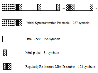
Each transmission of a MIL-188-110B message begins with a synchronization phase (preamble) which includes 287 8-PSK symbols. In the preamble the modem setting, i.e., user data rate and interleaver size, is coded. This auto baud feature should be used to configure the modem to decode the data bits. After the preamble the user data bits are transmitted in blocks of 256 symbols paired with 31-symbol mini-probe blocks. After 72 user data – mini-probe pairs a 103-symbol mini-preamble is inserted. The number of data blocks in a transmission is in principle unlimited. A unique bit pattern (in hexadecimal number, 4B65A5B2, MSB first) is sent to mark the end of message (EOM). The EOM sequence is followed by flush bits, for flushing the FEC coder and for the complete transmission of the remainder of the interleaver data block
The FEC and the interleaver are used to combat the effects of fading, frequency drift, multi-path effects, and burst noise etc. in the HF transmission. The mini-probe and regularly re-inserted mini-preamble are transmitted to help keep the receiver synchronized.
The MIL-188-110B decoder processes all the above settings except 12800 bps. This setting is usually not to be used for reliable data transmission, because it has neither FEC nor interleaving. Generally MIL-188-110B transmits the user data in binary mode, i.e., it does not care which type of data is transmitted. This should be defined by the protocol layer using the MIL-188-110B mode. For this reason the decoder just displays the user data in BINARY, HEX, ASCII ASYNC, ASCII ASYNC (7 Data bits and 0 Stop bit) or ASCII SYNC format which may be selected from Options/Message Type.... The decoder stops displaying data after the EOM bit pattern is received.
In the HEX display mode, the decoded binary data is just displayed as is, MSB first. Display is terminated when more than 25 NULL hexadecimal characters have been received.
In ASCII ASYNC mode, the bit stream is searched with an ASCII ASYNC structure, i.e., one start bit (0), 8 data bits and at least one stop bit (1). The 8 data bits are transmitted LSB first. In addition to the EOM pattern, the display will stop if more than 300 NULL characters are received or if the async data structure is violated more than 80 times.
In ASCII ASYNC (7 Data bits and 0 Stop bit) mode, the bit stream is searched with another ASYNC structure, i.e., one start bit (0), 7 data bits. The 7 data bits are transmitted LSB first. In addition to the EOM pattern, the display will stop if more than 300 NULL characters are received.
In ASCII SYNC mode, each 8 bits (LSB first) represent one ASCII character. The display will stop if the EOM pattern is received or if more than 20 NULL characters are received.
Tuning the decoder
The decoder processes the signal in both SSB settings: USB and LSB. The sideband can be selected with the Polarity option in the menu: NOR means USB and INV means LSB signal.
The center frequency of the decoder should be set to 1800 Hz when the receiver is correctly tuned to the sending station. Small frequency variations are automatically compensated for in the decoder. The center frequency of the decoder can be adjusted to ± 400 Hz from its normal setting. By using the bar graph, any remaining frequency difference can be compensated for by fine-tuning of the receiver frequency or by adjusting the center frequency of the decoder.
Dedicated Phase Plane
See MIL-188-110A.